 |
| - You're flying! How? - Python! ( https://xkcd.com/353/ ) |
Continued
 |
| A satellite or a bowl of spaghetti? |
Plan A: 2 Pi in a Pod...
The initial plan was for 2 Raspberry Pi using a serial communication protocol. The Model A+ does not have an ethernet port. Of course a Raspberry Pi 2 has one, and is more powerful, but it also consumes a lot more power than the A+. Our battery pack would have had to be much larger if we went down that path, and that meant significantly heavier. We had a goal of 2Kg for the payload itself, and we were getting close, so serial it was...
Serial communication
 |
| DB25 (serial or parallel) |
 |
| DB9 (serial) |
Many early personal computers typically had two interfaces, either built in or available through an expansion card: a serial (either a DB9 or DB25 connector) and a parallel interface (either a DB25 or 36 pins Centronics connector, aka IEE1824). The parallel interface was typically used for printers (and great for DIY DACs with resistor ladders, but that's a story for another time), while the serial port was mostly used for modems or scientific equipment.
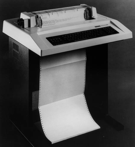
RS-232 was introduced in 1962, so it's been around for quite a while now. Many serial connections were actually TTL (5V), such as on the Digital Decwriter III, but it was quite easy to convert them to a +/- voltage range (and even more so since the mid 80s with ICs such as the MAX232). The initial purpose was to connect a DTE (Data Terminal Equipment), a fancy way of saying a computer, and a DCE (Data Communication or Circuit-terminating Equipment).
On a DB9 connector, the pins would be (DB9 male connector pictured):

RxD is Receive Data and TxD is Transmit Data. What if you need to connect two DTE together? You need a Null-Modem adapter or cable. The simplest Null-Modem circuit requires 3 wires (2 if you can guarantee the ground on each end to be the same):
 |
| GND(7) to GND(7), TxD(5) to RxD(4), RxD(4) to TxD(5) |
Raspberry Pi Header
The Raspberry Pi doesn't have a DB9 or DB25 connector. But if you look at the 40 pin header, notice on the top row, the 4th and 5th pins:
 |
| Raspberry Pi Model A+ with pinout as overlay |
TXD and RXD. It is a serial port, but it is *not* RS-232 compatible as far as voltage levels are concerned (a 1 is marked by a negative voltage in the range -3V to -15V, and a 0 by a positive voltage in the range +3V to +15V), as it is a TTL interface (a 1 is marked by a positive voltage, either 3V3 or 5V and a 0 is marked by 0V). But that is fine, we are only connecting to another Raspberry Pi.
The primary issue with this serial port is that the Raspbian operating system has a console (TTY) associated it. Meaning that you could connect this to a computer, with the right cable, and see the boot process and get a console prompt, and be able to type commands, as if you had a keyboard and monitor connected directly to the Raspberry Pi.
In our case, however, we want to use the port for something else, our own communication network, so we have to disable this feature. It was once a manual process, and I had written a script to do it, but...
Configuration
 |
| sudo raspi-config |
The raspi-config now has an option under the Advanced Options selection to disable the serial port console, so we can use it directly:
 |
| Advanced -> Serial |
Plan B: A Pi cluster
By using a pair of Raspberry Pi, the communication process is pretty straightforward. With two nodes, we can use SLIP or Point to Point Protocol (PPP). Initially, this was the thought for NSC-01 and we would not have to write the code for the network layer. |
| 6 Raspberry Pi cameras |
 |
| 1 Infrared Raspberry Pi camera (pointing down) |
But without a functioning camera switcher, the only option was to use one node per camera (each Raspberry Pi has 1 CSI camera connector, even thought the Broadcom chip supports 2 - most cell phones have a front and rear camera). With 7 CSI cameras in total, that meant 7 Raspberry Pi.
Time to dig in our bag of tricks...
Token Ring
 |
| 4 Node token ring network architecture |
As I was going through the options, I started thinking about good old IBM Token Ring (and FDDI). Conceptually, at least. I wasn't going to make something compatible with 802.5, but instead reuse the concept with the serial UART, transmit to receive from one node to the next.
Conceptually, a node is always listening to the serial port. Is this data for me? (if it's a broadcast or if it's addressed to me) If not or if a broadcast, I send it right away to the next node, and process it if it is addressed to me. So let's get into the details.
The diagram
 |
| 7 Raspberry Pi networked together |
In the diagram above, I didn't have a Raspberry Pi model A+ for fritzing, so I used the closest thing for our purpose, a Raspberry Pi model B+. Both of them have a 40 pins GPIO header. First row at the top, from left to right has 5V, 5V, GND, TxD and RxD. We'll stop there for right now.
Here I've simply connected node 1 TxD to node 2 RxD (blue wire), node 2 TxD to node 3 RxD (pink), node 3 TxD to node 4 RxD (brown), node 4 TxD to node 5 RxD (cyan), node 5 TxD to node 6 RxD (orange), node 6 TxD to node 7 RxD (yellow) and finally node 7 TxD to node 1 RxD (green), in a nice circular (or ring) fashion.
The GND are not daisy chained from one Pi to the next, because they are all powered by the same source, through their microusb plugs.
Initially, I tried to power the Pi directly from the 5V pin on the GPIO header, but the signal was decoding only partly. By further connecting the 3.3V (that was key, the UART operates at 3V3 so the HIGH signal was not detected reliably when powered with only 5V) and GND together, it made it more reliable, but also more complicated. I reverted back to powering all the 7 nodes using microusb (as detailed in the previous article).
Python
What's great about Raspbian is that not only do we have Python installed, but Python 2.x and 3.x are there, along with many things that are normally optional, such as pygame, pyserial, RPi.GPIO etc. Batteries are quite definitely included with Python on the Raspberry Pi.
Still, for the networking software, we did install two modules from pypi using pip3 (we are using Python 3), docopt and sh.
For the bulk of the development, I used a Raspberry Pi Model B+ connected to my laptop and to a second Raspberry Pi using the serial port and the network switch. That way my laptop could see both Raspberry Pi and I could push new versions of the software using scp.
I also had a "field" version, in case I needed to do last minute changes:
 |
| Raspberry Pi sidekick in sidecar configuration (DHCP server on laptop) |
Docopt
For example, in the case of the network controller, token.py, it accepted one argument, the node number. In the future, we'll probably derive the node number from a personality module on the GPIO header, but it was a simple solution that could be done in software, not adding any weight to the payload. The downside was having to keep track of all the microsd cards:
 |
| micro SD card transport - For nodes 1 to 7 plus 1 backup |
And, so back to docopt, here is how it was used for token.py. At the top of the file, after the shebang line (so the script can be an executable), I included the docstring which defines the interface (lines 2 to 5), which is a required field <address>. This is a simple case, but as cases get more complicated, it really pays off to use docopt.
Then on line 14 I import the docopt module (I group imports alphabetically first by what's included, then a blank line, then again alphabetically I add the imports that have to be installed - just a convention):
1 :  #!/usr/bin/env python3
2 :  """
3 :
4 :  Usage: token.py <address>
5 :  """
6 :  from datetime import datetime
7 :  import logging
8 :  from logging.handlers import SysLogHandler
9 :  import RPi.GPIO as gpio
10:  import serial
11:  import subprocess
12:  from time import sleep, time
13:
14:  from docopt import docopt
I then conclude the script by passing the arguments that docopt figured out are there (and validated) in the docstring (__doc__), to the main function:
168:  if __name__ == "__main__":
169:    arguments = docopt(__doc__)
170:    main(arguments)
171:
And how does one use it in the code itself? In the body of the main function I do the following:
97 :
98 :  def main(args):
99 :      my_addr = int(args['<address>'])
100:
 |
| In case an air traveler wants to check our website... |
SH
sh: is a full-fledged subprocess replacement for Python 2.6 - 3.4 that allows you to call any program as if it were a function:`python from sh import ifconfig print ifconfig("eth0") `
Continuing with the code in token.py, you simply import what you need from the shell and sh transparently builds a function for you to call. In this case I needed access to date and rmmod:
1:  #!/usr/bin/env python3
2:  """
3:
4:  Usage: token.py <address>
5:  """
6:  from datetime import datetime
7:  import logging
8:  from logging.handlers import SysLogHandler
9:  import RPi.GPIO as gpio
10:  import serial
11:  import subprocess
12:  from time import sleep, time
13:
14:  from docopt import docopt
15:  from sh import date, rmmod
Then further down in the code I can call date() to call the actual date command from the OS so it is not only in the right format, but in the right timezone (there are other ways to do this, but sh was going to be used heavily for gathering stats, so it made sense to introduce it here):
154:      # synchronize time
155:      s = str(date())+' \n' # from the OS
156:      bin = bytes(s, "ascii")
Pyserial
So, how about accessing a serial port in Python? And are there things to keep in mind when using Python 3?
First thing first, we import serial (line 10). This module is already installed on the Raspberry Pi.
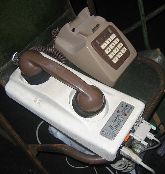
Then, within the body of the main function, we establish a serial connection (line 101). We specify the device that corresponds to the serial UART. This is /dev/ttyAMA0. We also specify the bitrate, expressed in bits per seconds (bps). 115200 is the fastest we can use with the default clock settings for the UART, and is what was used for the flight. As a reference, acoustic coupler modems worked at 300 bps...
We felt that at higher rates it might not give us as reliable a signal, but we will experience with faster rates on future flights (we only had time to do 1 flight within the Global Space Balloon Challenge window). Back in 2012, Gert Van Loo stated:
"The UART and the SPI can be driven by DMA so there is no SW limitation.The real maximum for all those interfaces is only set by the signal integrity.This is certainly the case for I2C as it has to use pull-up resistors to get the signals high again.I know the clocking is rather confused. I built the damn chip and I still have no idea how to control all the clocks.The clocking structure is very complex with a limited number of resources (PLL's) which are used for aplethora of things to drive. (A quick count shows 36! clocks being generated) There will be many cases where it is just not possible to give you ALL the frequencies you want."
And in fact, it is possible to get up to 921600 bps (8 times what we used) in a controlled environment, at the OS level In an environment full of RF, including a 10W 2M transmitter, with a python module, I'd be happy with 4 times (460800) or even twice (230400) our rate. If nothing else, it would drive our latency down some.
Wow, that was quite the detour, anyway, back to our establishing the serial connection. The last thing we specify on line 101 is timeout=1. This is a 1 second timeout. We will be blocking on reads (line 113), but don't want to wait more than 1 second for the data.
In the original token ring world, a frame is defined in the following way:

A start delimiter, access control, frame control, destination address and source address, then the data, and finally a frame check sequence, end delimiter and frame status. I found this later, after I designed the frame for our system, and it is interesting that it is quite similar, in functionality, but implemented slightly differently.
In our case, the frames are small in size, they should never go above 1 second to transmit. And if they do, then we kick out that partial request and the balance of the request and we'll get the next one that is complete. So, we assume that if we get a full frame, the first byte is always first, and the frame always conclude with a newline (that way the ser.readline() returns before the 1 second timeout). We thus avoid the start delimiter (the end delimiter is newline).

The first byte for our protocol is the source address (1 byte = 254 addresses, 0 and 255 have special meaning). The second byte is the destination. On an 8 node setting (the default), this is a bitmask, and 255 (FF) is broadcast. On a "large" cluster, this address is the individual node address, and 255 (FF) is still broadcast. You gain number of nodes, but loose directed broadcast (say, I want to send something to node 1, 2 and 6, I would use a destination of 9 in the 8 node mode, but in extended mode I have to send 3 individual frames). Then the status. This can be a static status (the packet gets back to the originator) or a counter status (each time a node processes the frame, it decreases the status) or a no status needed, where the nodes simple forward the original frame, but do not send a status. This is followed by a command. This allows for shorter data segments, since we just need the variable part of the command. Finally, the data, a variable number of bytes terminated by newline (\n).
As we get to higher speeds, I will definitely add the frame check sequence of the original token ring to our design.
In the original token ring world, a frame is defined in the following way:
A start delimiter, access control, frame control, destination address and source address, then the data, and finally a frame check sequence, end delimiter and frame status. I found this later, after I designed the frame for our system, and it is interesting that it is quite similar, in functionality, but implemented slightly differently.
In our case, the frames are small in size, they should never go above 1 second to transmit. And if they do, then we kick out that partial request and the balance of the request and we'll get the next one that is complete. So, we assume that if we get a full frame, the first byte is always first, and the frame always conclude with a newline (that way the ser.readline() returns before the 1 second timeout). We thus avoid the start delimiter (the end delimiter is newline).
The first byte for our protocol is the source address (1 byte = 254 addresses, 0 and 255 have special meaning). The second byte is the destination. On an 8 node setting (the default), this is a bitmask, and 255 (FF) is broadcast. On a "large" cluster, this address is the individual node address, and 255 (FF) is still broadcast. You gain number of nodes, but loose directed broadcast (say, I want to send something to node 1, 2 and 6, I would use a destination of 9 in the 8 node mode, but in extended mode I have to send 3 individual frames). Then the status. This can be a static status (the packet gets back to the originator) or a counter status (each time a node processes the frame, it decreases the status) or a no status needed, where the nodes simple forward the original frame, but do not send a status. This is followed by a command. This allows for shorter data segments, since we just need the variable part of the command. Finally, the data, a variable number of bytes terminated by newline (\n).
As we get to higher speeds, I will definitely add the frame check sequence of the original token ring to our design.
10 :  import serial
11 :  import subprocess
12 :  from time import sleep, time
13 :
14 :  from docopt import docopt
15 :  from sh import date, rmmod
[...]
97:
98 :  def main(args):
99 :    my_addr = int(args['<address>'])
100:
101:    ser = serial.Serial('/dev/ttyAMA0', 115200, timeout=1)
[...]
111:    while not master:
112:      logger.debug("I am SLAVE") # Everywhere but node 1
113:      tokens = ser.readline()
114:
115:      if len(tokens) == 0:
116:        logger.debug("No token received in the past 1 second")
What about writes? As an example, in the case of the master controller, it starts its job by sending a KEEPALIVE frame. This is defined by a series of bytes on line 36. Source is 01 (master node), destination is 255 (FF) broadcast, status is FF (no response needed), then command 05 which is a keepalive. Data segment is of length 0 since \n is encountered immediately. This is the shortest well formed frame that can be sent. And that is what the master controller sends on line 152 using ser.write. As long as we keep everything as type bytes, the serial module works well in Python 3.
Pretty simple, overall (!). Well, considering this was all designed over the course of a handful of days. Python really helped.
[...]
36:  KEEPALIVE = b'\x01\xff\xff\x05\n' # keepalive packet
[...]
149:    # I am master, or I am taking over
150:    if my_addr == 1:
151:      sleep(15)
152:      ser.write(KEEPALIVE)
153:      sleep(1)
We will be creating a module for reuse out of the token.py application, so that other people can use a serial token ring setup themselves. This should be published to pypi. We'll also publish a demo implementation for a master/slave setup.
Deadman's Switch
I'm concluding this article here, as it is already quite long. But I invite you to read about a most interesting device, the Deadman's switch. This was used in our High Altitude Balloon, but it can be used in all kinds of scenarios. Read about it here: http://raspberry-python.blogspot.com/2015/04/deadmans-switch.html
And don't forget to check back regularly for more updates, such as part 3 of this series of articles (the data gathering aspects).
Francois Dion
@f_dion
And don't forget to check back regularly for more updates, such as part 3 of this series of articles (the data gathering aspects).
Francois Dion
@f_dion


